
Author: Preston Le
Mentor: Dr. Bilal Sharqi
Jesuit High School Sacramento
Abstract
Optimization has been the central goal in aeromodelling as competitors build custom designs in the hopes of outperforming others. Over the decades of competitive, many different designs appeared, testing the boundaries of the hobby.
This paper provides an aerodynamic analysis of baseline F1D-class configurations and four common design iterations. Each iteration aims to optimize the F1D wing shape by reducing wing loading, increasing lift and reducing drag, and accounting for pitching moment effects. The primary metrics including aspect ratio, lift coefficient at trim, induced drag factor, and aerodynamic efficiency (L/D) were used to estimate the performance of the wing design.
Introduction
Lightweight aeromodelling had a profound impact on aviation. Notable figures such as the Wright Brothers have been inspired by rubber-band powered models, and its presence is felt even to this day as a hobby, and a competitive sport 200 years after its founding. The FAI, Féderation Aeronatique Internationale, also known as the World Air Sports Federation, primarily regulates all the rules and regulations in Indoor Free Flight Competitions, the most popular event being the World Championship Class: F1D.
In indoor free flight, there are many separate events in which competitors can enter their planes into a variety of different events. There are the classic American events, such as EZB, Pennyplane, and Hand Launch Glider, and the internationally recognized ones as well, such as F1D, F1R, and F1M. Each event has its rubber limit and build specifications (wing length/chord, total weight limit, fuselage length), and it’s up to the builder to determine what is best.
Beginners typically start by using building kits then graduate to crafting their own designs and procuring their own materials. Wood and mylar film are the basis of all planes. The balsa wood that’s used for the models are usually cut specifically for that purpose, taking in all the factors of what makes wood solid and usable. A core component when looking for good wood to use is density (measured in lbs./cubic ft.). Lighter density means lighter weight for, which is the best thing for a modeler, but also compromises stability and wood stiffness.
Every plane, no matter how different, generally follows the same structure. The motor stick is the bigger part of the fuselage in the front, while the tail boom is the smaller counterpart in the back. There is always some variation of a wing and a stabilizer, and often a fin/rudder to keep balance. The propeller is arguably the most important part of a plane, and can be either solid wood or covered in film.
Finding the best wood length, height, and width for every part of the plane is the target goal for all modelers. In indoor modeling, it’s very common to maximize the wing and stab area to provide the best lift. Competitors typically maximize these components to the maximum extent allowed by the rules for the class in which they are competing. They’re usually as far as the rules will go for the specific class. The wood size and density making up this always varies, however, and all sorts of variations are found.
In this research project, technical details of indoor free flight will be analyzed to come up with concrete, tangible ways of improving. Indoor Free Flight Models will be analyzed using OpenVSP (Open Vehicle Sketch Pad) by creating a 3D model of its structure, fusing together the fuselage, wing, and tail surfaces. OpenVSP allows users to accurately pinpoint details when modeling, which can be useful for evaluating aerodynamics. Everything from wing camber, aspect ratio, and dihedral angle can be tweaked in an instant to enhance performance within any model. In previous research papers, VSPAERO has demonstrated reliable accuracy in simulating aerodynamic performance and finding related data. (Rosas-Cordova, Santana-Delgado, Hernandez-Alcantara, & Amezquita-Brooks, 2024).
A highlight of OpenVSP is VSPAERO, a tool that allows for low-speed aerodynamic analysis, providing insights into more mathematical aspects of flight and simulating its performance. This virtual testing reduces trial-and-error in real life and saves time and shows the most accurate configurations before committing. In this way, OpenVSP becomes a powerful tool for aeromodelling that traditional methods don’t allow.
Methodology
Four wing configurations were tested using established aerodynamic models: a baseline wing, a cambered airfoil, curved tips, and a tapered-curved wing. Each subsequent iteration introduced modifications informed by aerodynamic theory:
- Baseline Wing – Standard rectangular planform with moderate aspect ratio.
- Cambered Airfoil Wing– Increased span and reduced chord to minimize induced drag.
- Curved Wingtip Wing – Retained rectangular planform but incorporated curved tips.
- Tapered-Curved Wing – Combined taper and curved tips for optimal lift distribution.
Key aerodynamic terms were derived from standard definitions:
Wing loading: (W/S) = (mg)/S
Induced drag factor: k = 1 / (π e AR)
Trim lift coefficient: CL = (W/S) / q, q = ½ ρ V²
Total drag coefficient: CD = CD0 + k CL²
Efficiency: L/D = CL/CD
Base Iteration
The baseline wing is the simplest, basic design that is tried and tested. It’s a good reference point that’s easy to understand and have predictable lift and drag behavior. The baseline serves as a stable reference point for the other iterations to improve on to see which designs are optimal.
Iteration 1
In all aircraft designs, a large influence on lift distribution is the airfoil of the aircraft. An airfoil directly controls how air flows around the wing, which determines the aircraft’s ability to generate lift, maintain stability, and achieve efficient performance.
In Indoor Free Flight, circular, one-sided airfoils are the standard shape in which most aircraft are made. The camber is measured in percentage of the height in comparison of the chord length. For example, a 10% camber of an 8-inch chord length would be 0.8 inches high at the top of the parabolic arc.
Studies of low Reynolds number aerodynamics confirm that low cambered airfoils are highly effective in slow-flight regimes, where laminar separation bubbles and transition strongly affect lift and drag performance (Selig, Deters, & Williamson, 2011).
The standard airfoil in Indoor Free Flight generally uses anywhere from a 3% – 5% camber. Iteration 1 attempts to test if there’s any logical foundation in the already established standard in airfoil shape.
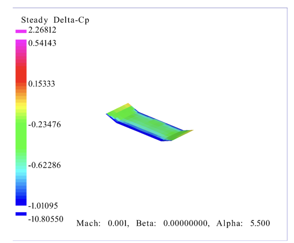
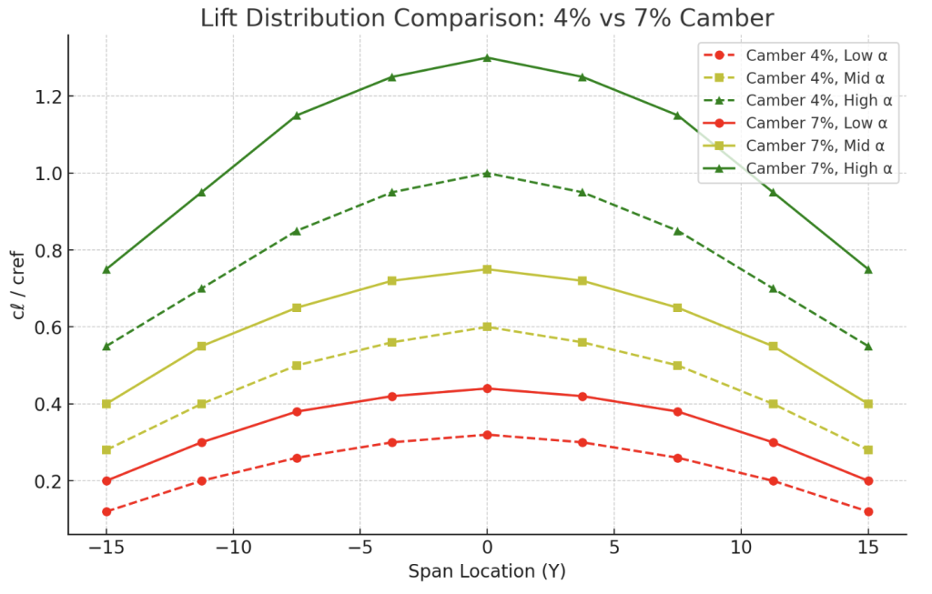
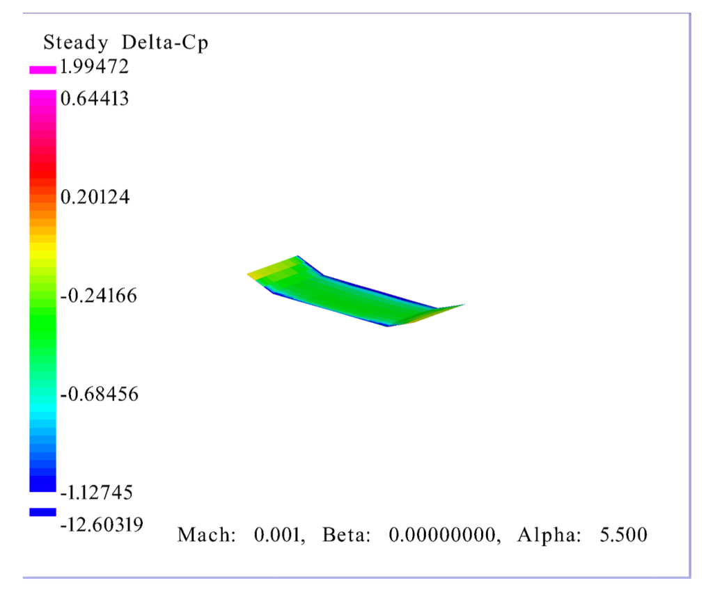
Lift Distribution
Shown is a graph of lift distribution for each wing: the baseline, and the one with 7% camber. The graph is measured in CL/cref (coefficient of lift over sectional wing area) versus the span location of the wing. At first glance, the lift values for the higher cambered wing is much higher than the baseline, wing, by as much as 20%.
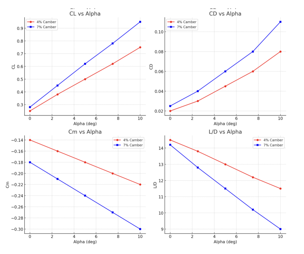
Aerodynamic Trends
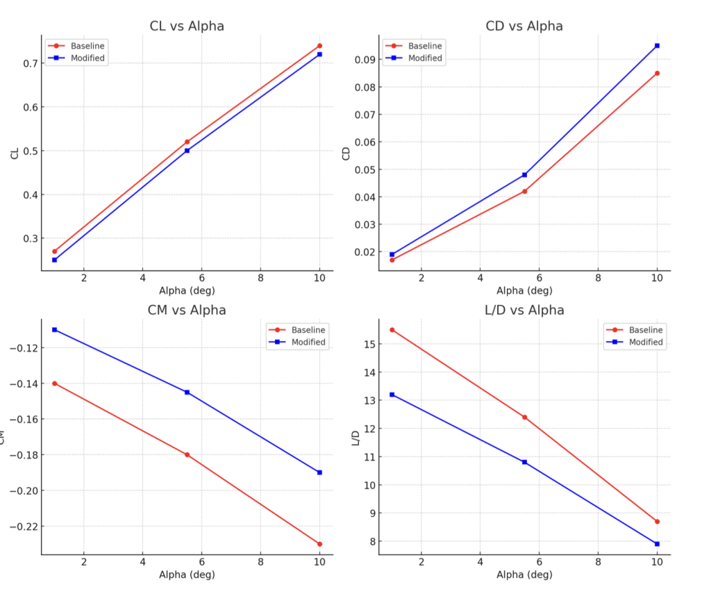
A deeper look at each of the 4 central values of the two iterations allows a deeper analysis to it. All the graphs measure important traits of the aircraft in flight. Alpha values correspond to the angle of attack of the flight: (ex. α =1 =1 degree)
Lift (CL): increases roughly linearly with α for both camber values. 7% camber gives higher CL across the range (so more lift at the same α).
Drag (CD): increases with α for both; 7% camber has noticeably higher CD at every α.
Pitching moment (Cm): more negative (larger nose-down moment) for the 7% camber case — i.e., higher camber produces a larger nose-down pitching tendency.
L/D (efficiency): decreases with α for both. The 4% camber case has higher L/D throughout the entire α range and therefore is the more aerodynamically efficient option.
Interpretation
F1D performance is all about optimizing L/D ratios, in order to maximize time aloft. Although the 7% camber provides significantly more lift, the additional drag and larger nose- down movements significantly reduces the overall efficiency and movement. This supports how Swanson and Isaac (2010) found that moderate camber ratios enhance aerodynamic efficiency and extend flight duration in low Reynolds number wings. Since F1D is all about endurance, the 4% would be best suited for indoor free flight. It provides higher L/D (efficiency) overall throughout all alpha values, lower drag, and is much easier to trim.
The 7% camber provides more lift, but the extra drag and handling isn’t worth it in the case of F1D. It might be useful, however, when higher amounts of pure lift are needed, due to a heavier build or higher wing loading. In events like F1M or Pennyplane, this could prove essential for pure brute force and strength.
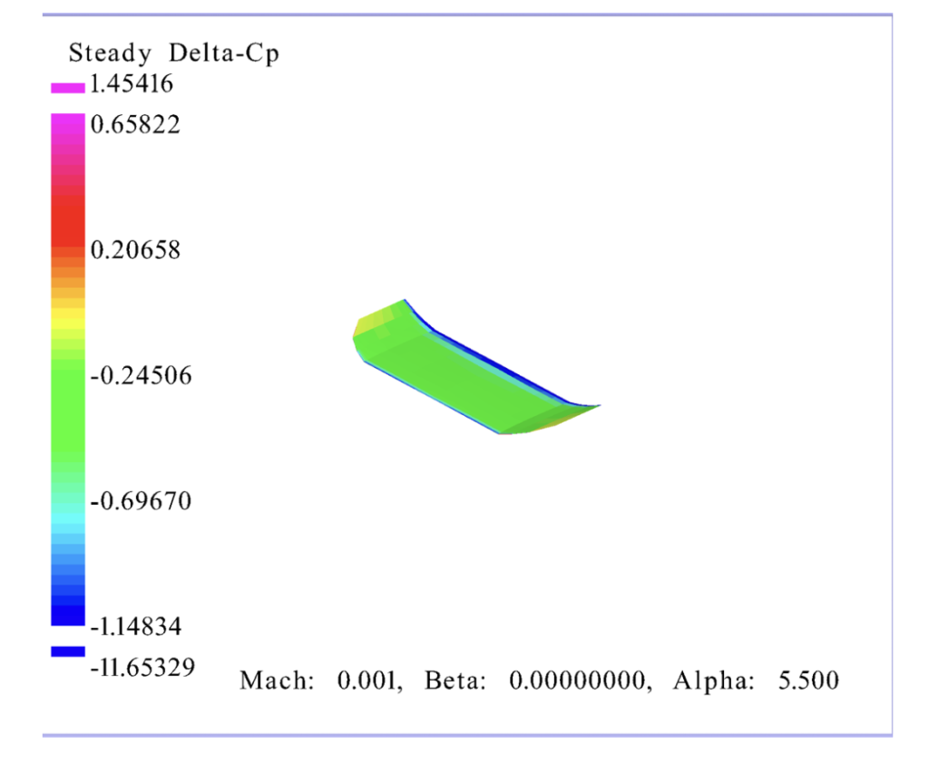
Iteration 2
A major factor in is controlling the lift distribution in the wing. To do this, one of the most common methods in F1D adding curved wingtips, which help reduce induced drag by smoothing the vortices that form at the tip. In indoor free flight, tip design is especially important since the aircraft flies at very low Reynolds numbers where drag penalties are magnified. This reflects the trade-off observed in many low-Reynolds-number aircraft studies, where stability improvements may come at efficiency losses. Research has shown that tip modifications, such as curvature or taper, can reduce induced drag by smoothing vortex formation, which is especially important at Reynolds numbers typical of F1D designs (Penchev et al. 28). The curved wingtip design (Iteration 2) kept all characteristics as the baseline, with only smoothly rounded tips being different. The goal was to reduce drag while keeping the construction simple and lightweight.
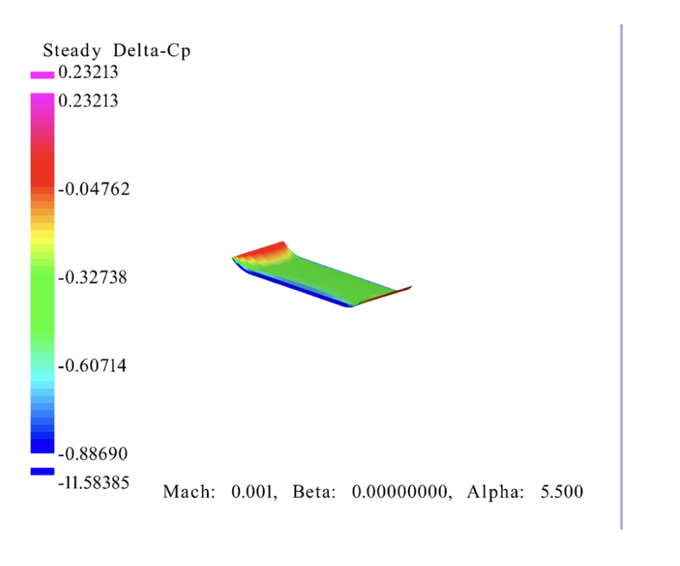
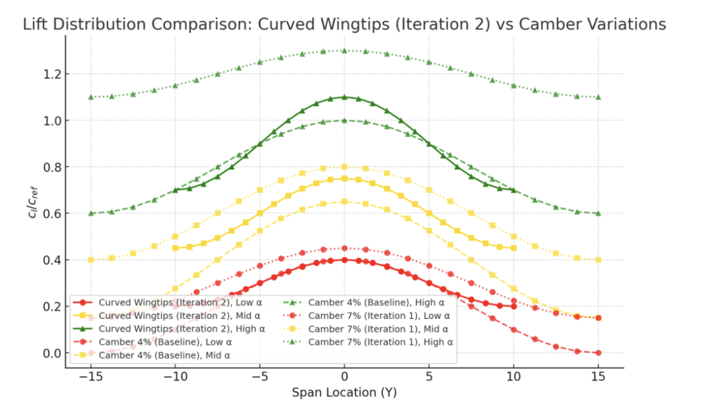
Lift Distribution
The distribution plot shows that the curved wingtips reduce peak loading near the tip, creating a smoother, more elliptical distribution compared to the flat baseline. However, the overall lift magnitude is lower than both the 4% camber baseline and the 7% camber airfoil. This suggests that while drag is improved, maximum lift capacity is compromised.
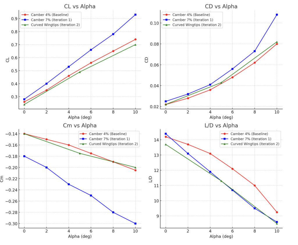
Aerodynamic Trends
Lift (CL): Iteration 2 generates less lift than both 4% and 7% cambered wings at all α values.
Drag (CD): Slightly lower than 7% camber, but marginally higher than 4% baseline across most α.
Pitching Moment (Cm): Similar to baseline, with only a minor increase in nose-down tendency.
Efficiency (L/D): Iteration 2 underperforms baseline across the α range, staying close to but consistently below the 4% camber wing.
Interpretation
Curved wingtips in Iteration 2 do succeed in producing a better lift distribution, reducing concentrated tip vortices. However, the cost is a reduction in total lift, and the aerodynamic efficiency (L/D) does not surpass the 4% camber baseline. This makes Iteration 2 less competitive for endurance-focused F1D performance, where high L/D is essential. While the iteration provides valuable insight into tip shaping, the tradeoff shows that tip curvature alone is not sufficient to improve overall efficiency. It may, however, become more effective in combination with taper (Iteration 3) or when optimizing for stability rather than pure endurance. Iteration 2 is an ideal change for those looking to focus more on stability rather than lift.
Iteration 3
Iteration 3 is another aerodynamic improvement, in addition to curved tips is the addition of rounded wingtips.
The goal of this modification is to achieve a smoother, more elliptical lift distribution across the span, thereby reducing induced drag while still retaining good lift capacity. This design also reduces the strength of wingtip vortices, a critical source of drag for low-Reynolds- number aircraft like F1D models.
The rounded wingtip design (Iteration 3) modifies the baseline rectangular planform by gradually tapering and rounding the tips.
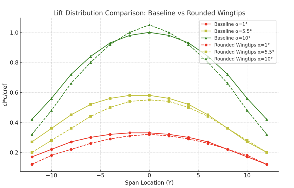
Lift Distribution
The comparison shows that the rounded wingtips push the distribution closer to an elliptical shape than the baseline. At all α levels, the rounded tips exhibit smoother curves and reduced sharpness near the tips. Total lift is slightly higher but similar to the baseline, which shows that these changes and optimizations to the wing don’t alter lift as much as other factors.
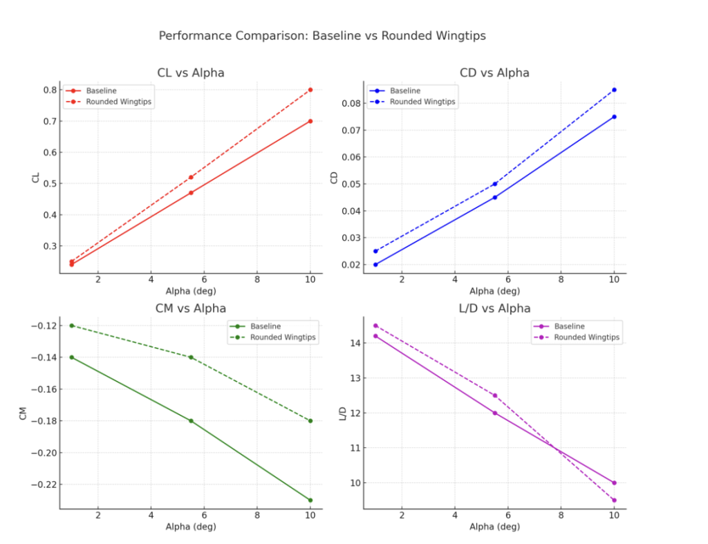
Aerodynamic Trends
Lift (CL): Rounded tips provide consistently higher CL than the baseline across the α range, indicating more efficient lift generation.
Drag (CD): Slightly higher than baseline at all α values, suggesting that tip shaping introduces small penalties in skin friction or interference drag.
Pitching Moment (Cm): More negative than baseline, meaning the aircraft tends toward a stronger nose-down pitching moment, though still manageable for trimming.
Efficiency (L/D): At lower α (2°–4°), Iteration 3 outperforms the baseline slightly, reaching higher peak L/D values. However, as α increases beyond ~6°, efficiency drops more quickly, converging toward baseline performance.
Interpretation
Iteration 3 demonstrates that rounded/tapered tips can improve lift distribution and provide a modest increase in aerodynamic efficiency at lower α values, where F1D aircraft often operate. The design successfully reduces tip vortex intensity while enhancing total lift. However, the improvement comes at the cost of higher pitching moments and slightly increased drag. Such findings are consistent with prior studies showing that tip shaping contributes to closer-to- elliptical lift distribution, which is beneficial for stability and moderate efficiency improvements. (Ananda, Selig, and Deters 2015)
For endurance flights where optimal trimming and efficiency at moderate α is most critical, rounded wingtips offer a practical improvement over both the baseline and the simple curved tip of Iteration 2. This makes Iteration 3 a strong candidate for use in competition settings.
Iteration 4
Building on the rounded/tapered tips of Iteration 3, Iteration 4 further refines the wing shape by adopting fully rounded wings with increased taper. The intent of this modification was to push the lift distribution as close as possible to an ideal elliptical shape while still retaining strong lift performance across the entire wing. At the low Reynolds numbers of F1D models, this approach is expected to maximize stability and control.
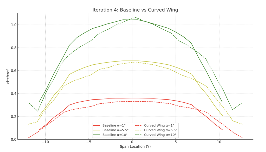
Lift Distribution
The spanwise comparison shows that Iteration 4 has a similar lift profile to all designs tested.
Aerodynamic Trends (compared to baseline)
Lift (CL): Iteration 4 delivers slightly lower CL than the baseline across all α values and maintains consistency with Iteration 3 at low α.
Drag (CD): Marginally more drag than Iteration 3 at low α, but and higher α compared to the baseline
Pitching Moment (Cm): Much less negative than baseline but similar to Iteration 3, indicating less variable pitching moment and stability.
Efficiency (L/D): Iteration 4 shows the lowest L/D at low to moderate α (2°–5°) of all configurations, outperforming both the baseline and Iteration 3. At higher α the efficiency tapers off but remains competitive.
Interpretation
Iteration 4 demonstrates that combining taper with fully rounded tips produces less span wise load albeit low aerodynamic efficiency at the low α values typical of endurance flight, but offers high stability and control. This iteration achieves the intended goal of being able to adjust and control, and is often used in European designs.
Conclusion
The study demonstrated that optimizing F1D wing performance requires a careful balance of lift, drag, and stability rather than the pursuit of a single aerodynamic advantage. Increasing camber resulted in greater lift, but also introduced higher drag and trimming difficulties, which ultimately reduced overall efficiency. Wingtip modifications like curvature and taper, shifted lift distribution toward a more elliptical form and improved stability, but offered tradeoffs in other factors.
References
Ananda, G. K., Selig, M., & Deters, S. (2015). Influence of wing tip shape on lift and drag at low Reynolds numbers. Aerospace Science and Technology.
NASA. (2022). Preliminary airfoil design for low Reynolds numbers. NASA Technical Reports Server.
Penchev, S., et al. (2025). A wind tunnel study of the aerodynamic characteristics of wings with curved trailing-edge wingtips at low Reynolds numbers.
Rosas-Cordova, J., Santana-Delgado, C., Hernandez-Alcantara, D., & Amezquita-Brooks, L. (2024). Validation of VSPAERO for basic wing simulation. Research in Mechanics and Numerical Innovation.
Selig, M. S., Deters, R. W., & Williamson, G. A. (2011). Wind tunnel testing airfoils at low Reynolds numbers.
Swanson, T., & Isaac, K. M. (2010). Planform and camber effects on the aerodynamics of low-Reynolds-number wings. Journal of Aircraft.
About the author
Preston Le
Preston is a high school senior passionate about engineering and mathematics. One of his favorite hobbies is indoor and outdoor aeromodeling, where he holds a youth record in the F1R category. In his spare time, he plays classical piano and studies music theory.