

Author: Ben Jiang
Mentor: Dr. Nikolaos Bouklas
Beijing No.4 High School International Campus
1. Introduction
Industrial production and manufacturing being the extraordinary enduring force that powered humanity for millions of years has came to a crossroad. According to the United Nations Environment Programme (UNEP), the global manufacturing sector accounts for approximately 22% of the total greenhouse gas emissions, with significant contributions from energy-intensive processes and material wastage.1 Not only does manufacturing produce enormous carbon footprints, unsustainable consumption also quickly deplete natural resources.2 Environmental issues brought significant attention on sustainable manufacturing. The United Nations promulgated the Seventeen Sustainable Development Goals that aligned with the course of this planet with the twelfth goal advocating for sustainable consumption and production.3
At this historical checkpoint, with manufacturing on the crossroads where the imperative sustainable practices intersect with the demand for efficiency and profitability, topology optimization comes in as a method to preserves both. Topology incorporates the optimization of material to derive advanced structural designs and generating “lightweight and high-performance configurations”.4 By running a finite element analysis, topology operates in altering the distribution of materials within a defined design space, guided by specified loads, constraints, and performance objectives. Exploring countless design configurations, this process uncovers the most efficient structural forms, often resulting in organic, complex geometries that traditional design approaches might overlook or underestimate.
Nevertheless, the production of such sophisticated geometry are restricted by conventional techniques of manufacturing and structural reliability, whereas 3D printing sets a paradigm for optimal design and sustainability. While traditional manufacturing methods obtains a low usage percentage, 3D printing manufactures with a 100% usage of material. Therefore, this method not only enhances structural performance but also reduces material waste, making it a cornerstone of sustainable manufacturing practices. By minimizing material consumption, manufacturers can significantly decrease their carbon footprint and resource depletion. Furthermore, the optimized geometries often lead to lighter-weight components, which contribute to energy savings during transportation and operation phases. These reductions in material usage and energy consumption align directly with global efforts to mitigate climate change and promote responsible, sustainable consumption within the manufacturing sector.
This paper explores the principles and applications of topology optimization in the context of sustainable manufacturing with actuation of 3D printing and finite element analysis. The paper examines how this innovative approach can revolutionize product design, enhance resource efficiency, and contribute to the broader goals of environmental sustainability. Through a case study of a household bracket design and theoretical analyse, the paper aims to demonstrate the transformative potential of topology optimization as a tool for achieving both technical excellence and environmental stewardship in manufacturing processes.
Keywords: Topology optimization, 3D printing, sustainable manufacturing, finite element analysis, geometry optimization, material reduction, carbon emission, energy efficiency, household bracket design, Polylactic Acid (PLA), Fusion 360, stress analysis, displacement, volume fraction, mesh product, shape optimization
2. Method and Material
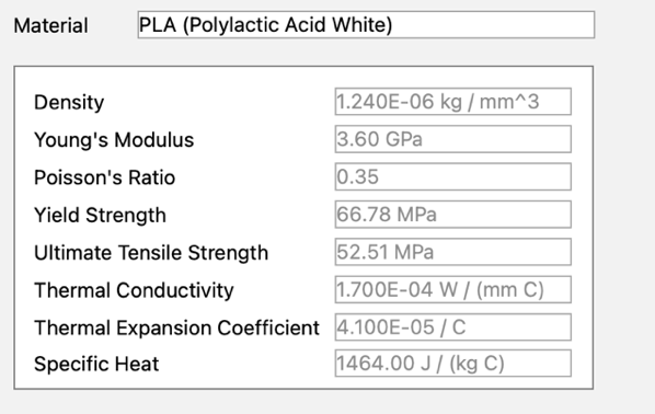
2.1 Applied material property
Polylactic Acid (PLA) is widely recognized in the realm of 3D printing due to its notable biodegradability, sourced primarily from renewable materials such as corn starch. It features minimal warping and shrinkage, which contributes to its compatibility across diverse 3D printing platforms. Although PLA may not match the mechanical robustness of certain conventional plastics, it offers satisfactory strength suitable for various applications.5 Characterized by a smooth, lustrous surface and available in multiple hues, PLA facilitates the creation of visually appealing prints. These properties are incorporated into Fusion 360 for the purpose of conducting finite element analyses aimed at simulating PLA behavior. 67
2.2 Utilizing Fusion 360
For finite element analysis, encompassing static stress analysis and topology optimization facilitates the simulation and analysis of real-world forces, heat, and other physical effects.
2.2.1 Initial boundary conditions
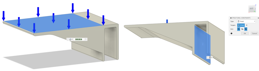
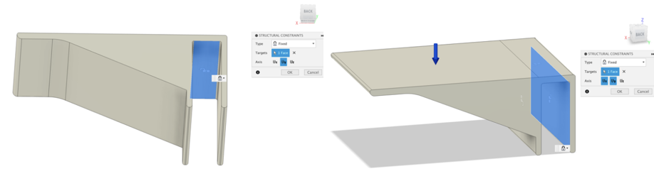
Boundary conditions were established according to real-world scenarios. Specifically, the back half bracket is affixed to a strip of wood from above, where weight and pressure are applied to the surface platform. The coordinate system is depicted below.
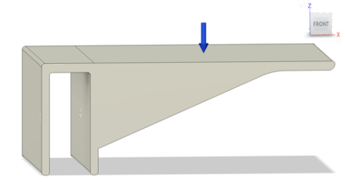
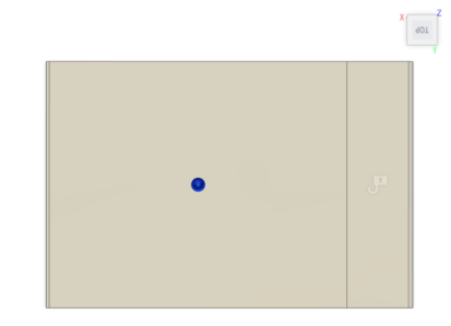
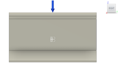
Figures 2, 3, 4: Front, top, right view of the initial model, blue arrow indicating the orientation and position of the pressure
To recreate the real-world contact and interaction between the bracket and the wooden bar, specific constraints were applied to the planes while subjecting the structure to a 100N pressure. Plane 1 (P1) is fixed along the X and Y axes, allowing unrestricted movement along the Z axis. Plane 2 (P2) is free along both the X and Y axes, facilitating movement within the XZ plane to simulate unrestricted space above. Plane 3 (P3) is fixed along the XZ plane due to constraint from the three-sided structure, while permitting movement along the Y axis. This boundary condition set up serves for both static stress analysis and shape optimization simulations.
3. Results
3.1 Version 0 (V0): Initial model without optimization
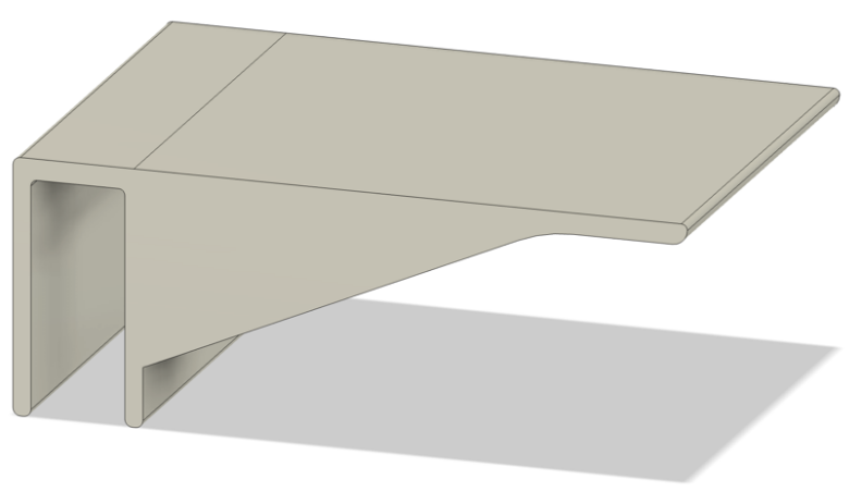
The model is configured by a simple press pull of a sketch. An abundance of material is concentrated under the main platform. Finite element analysis results for this version of the model are presented below. Mass of the initial unoptimized model is 1351.637g.
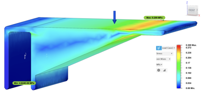
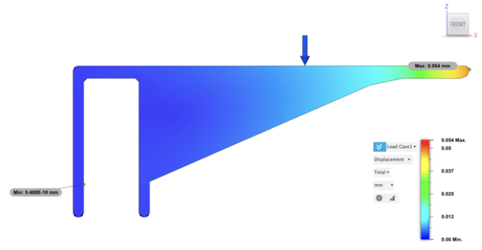
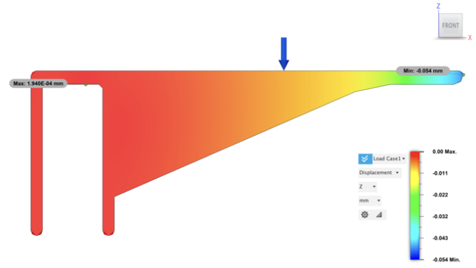
The maximum stress=0.289 MPa, maximum displacement (front)=0.054mm, maximum displacement (back) =5.400E-10mm, displacement Z (front in Z axis) =0.054mm.
3.2 Model with intermediate volume fraction (same boundary conditions)
3.2.1 Version 1 design (V1)
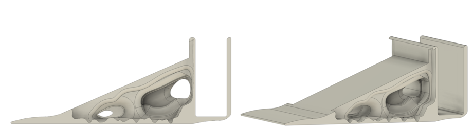
Under identical boundary conditions and while maintaining the main platform, a shape optimization analysis was conducted. The resulting model exhibits a mass and volume ratio of 59.5% compared to the unoptimized configuration. The model is displayed below.
A Static Stress Analysis is calculated with the new modified bracket and same boundary conditions (fixed planes, 100N pressure). Results are present below.
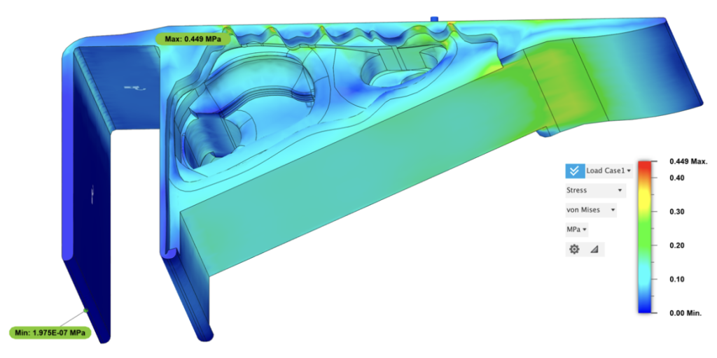
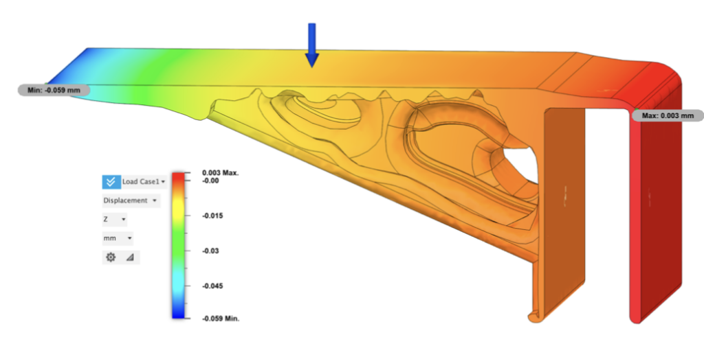
Figure 17: Static Stress Analysis (V1): Von Mises Stress
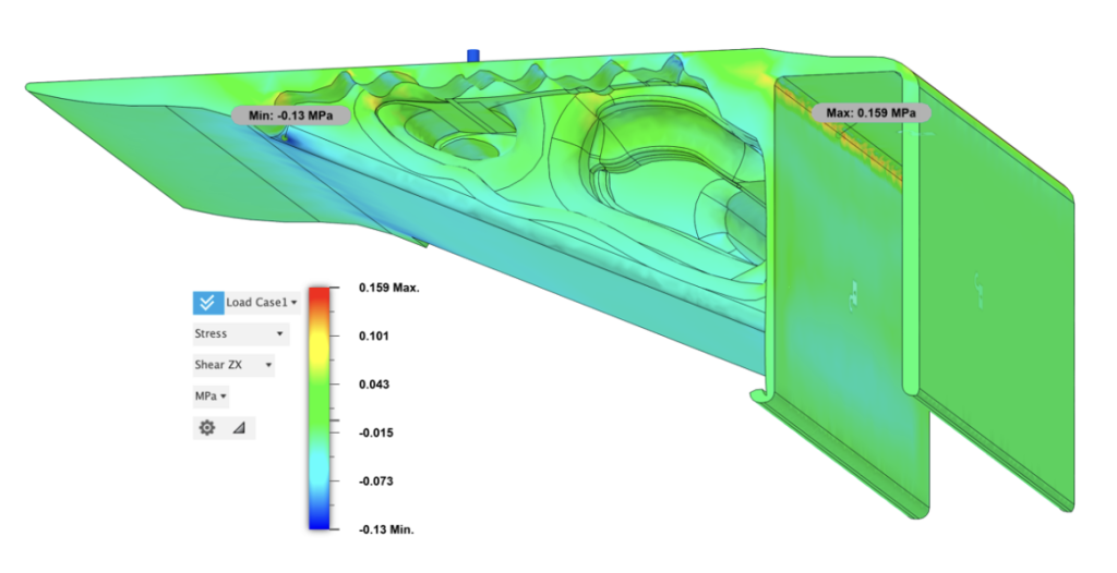
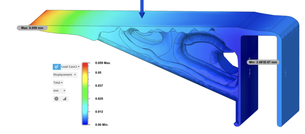
Maximum stress=0.449MPa, maximum shear ZX stress=0.159MPa, maximum displacement=0.059mm, maximum displacement in Z axis=0.003mm, minimum displacement in Z axis=-0.059mm
Stress is concentrated and conjugated in corners where material is scarce or experience a sudden decrease. As presented in the simulation results, the maximum stress (von mises), 0.449MPa appears at one of the concaving corners with only a thin layer of material. The total displacement is also little. As for the tail of the bracket, displacement in Z axis attains a slight tilt of 0.003mm, while the head displaces downward 0.059mm.
3.2.2 Version 2 design (V2)
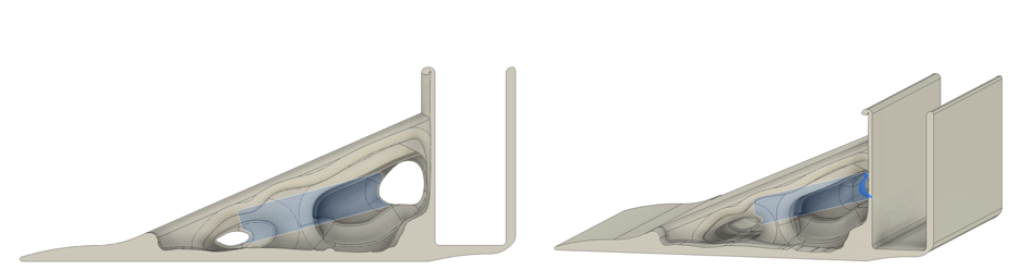
Due to stress concentration in concaving structure and irregular indents at the side surface of the plate, following modifications smoothed faces and verges, and injected a hollow tube to replicate the empty hollow present in the optimized mesh.
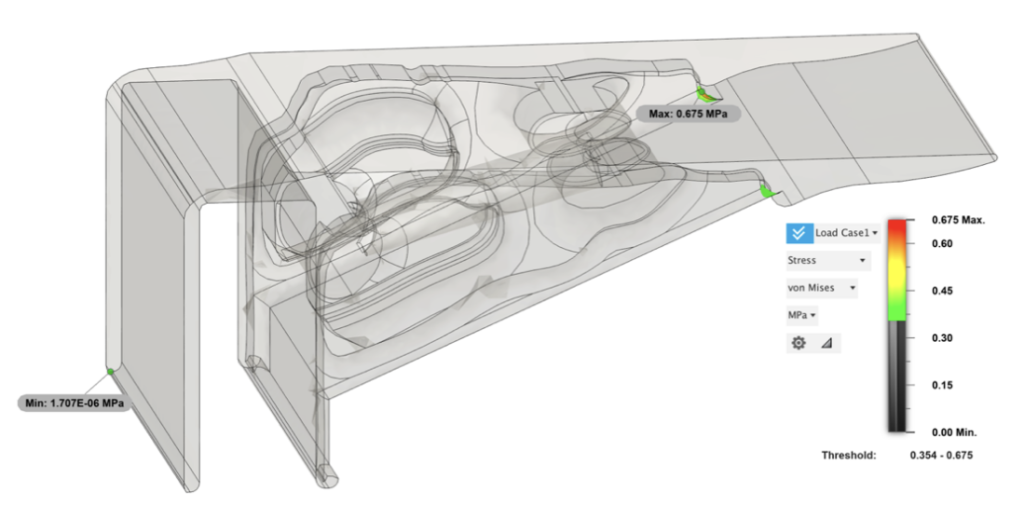
Following this revision, the flattened surfaces on the skirts of the bracket significantly reduced stress concentration. However, this revision added extra weight for the model to support and removed support in the solid region. Consequently, compared to the pre-revision state, the maximum stress increased by 0.226 MPa. The stress concentration also shifted to the corner where the platform merges with the main supporting structure. This point of convergence experiences a stress of 0.675 MPa, which is below the yield strength but noteworthy due to the concentrated stress indication. Stress levels range from 1.707E-06 MPa to 0.675 MPa in this area, with stress intensifying progressively from 0.35 MPa to 0.675 Mpa, which is half of the numerical scale.
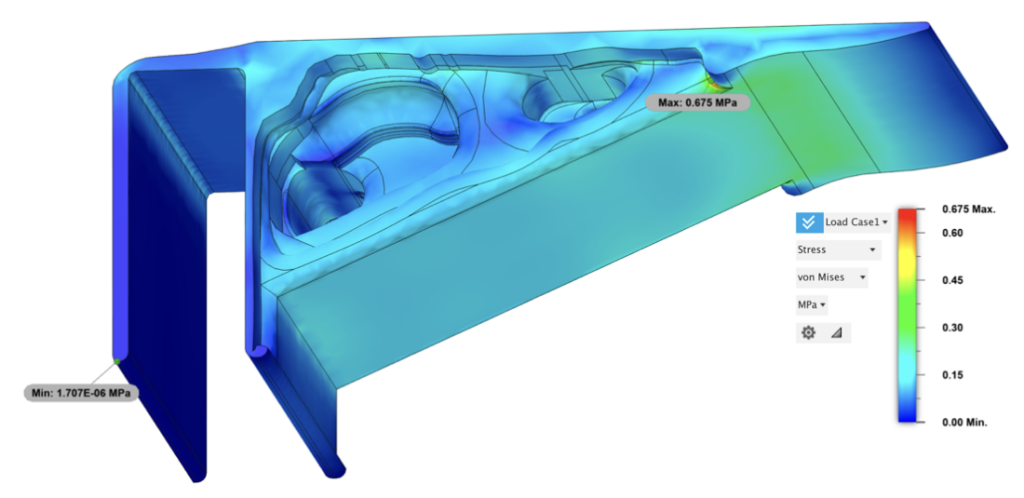
Figure 24: Static Stress Analysis (V2): Von Mises Stress
The model exhibited a slight variation in displacement, with an maximum overall head tilt of only 0.058 mm. This represents a reduction of 0.01 mm compared to the previous model, suggesting a more stable configuration despite the reduced support structure at the center.
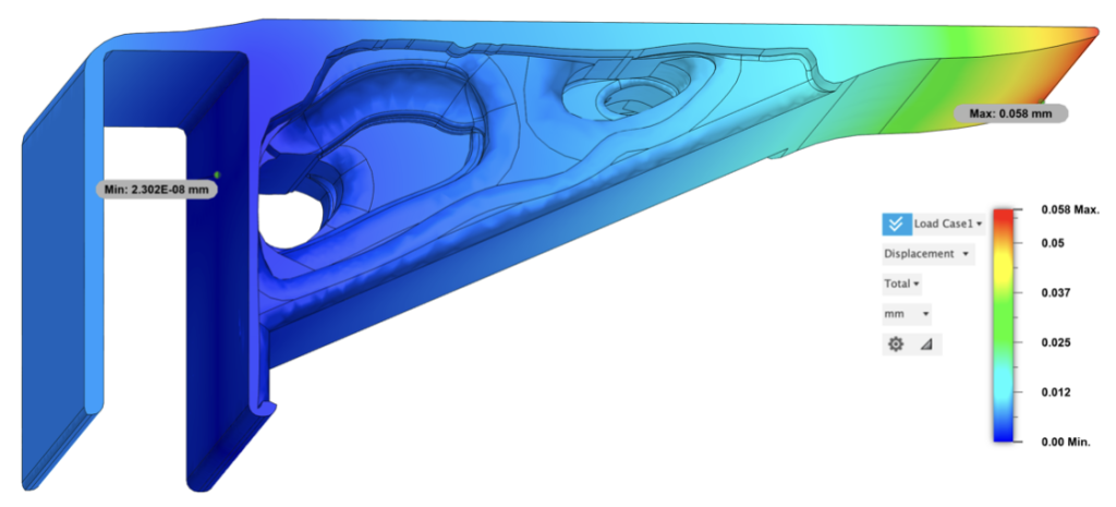
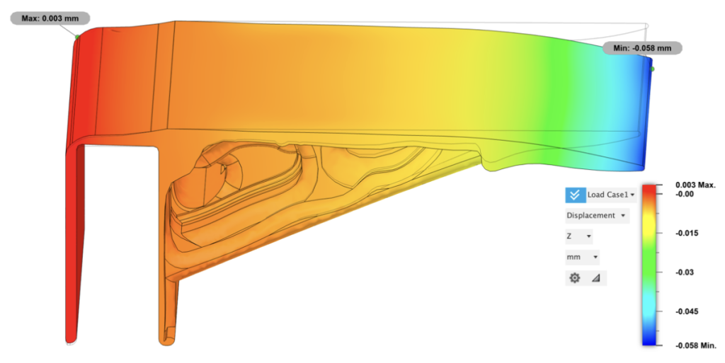
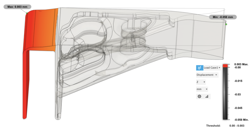
(exaggerated deformation presented)
In investigation of the hollow tube, stress concentration was observed at its upper half, which helped to support the structural load and reduced weight. The resulting mass is 794.015 g, corresponding to a mass ratio of 58.7% compared to the initial model, and a decrease of 0.08% compared to the previous bracket configuration.
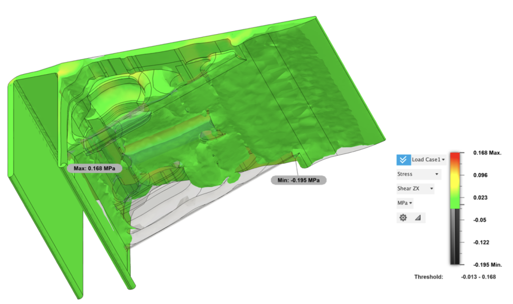
Figure 29: Static Stress Analysis (V2): Shear ZX Stress partial threshold (-0.013-0.168mm)
3.3 Model with low volume fraction (same boundary conditions)
3.3.1 Version 3 design (V3)
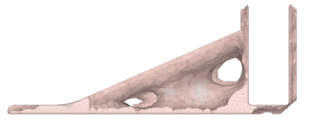
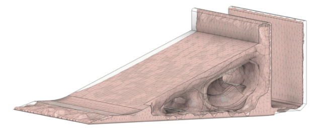
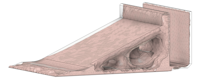
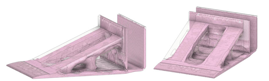
After rounds of modification, with the base structure of the Version 2 model, a second shape optimization simulation is conducted. A model attaining weight and volume fraction of 79.7% (with Version 2 being 100%) is converted into mesh and presented below. V3 of the bracket is designed based on the mesh structure.
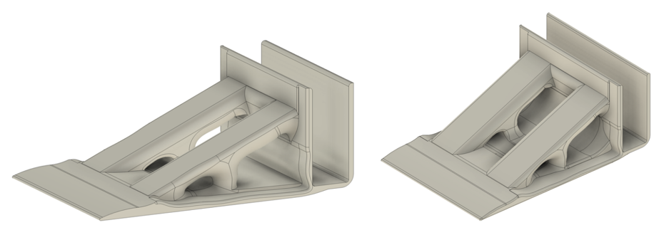
With a significantly lighter design, a fillet was incorporated into the structure to mitigate stress concentration, which could potentially exceed the yield strength and lead to bracket fracture or deformation. The new design demonstrates a mass and volume ratio of only 46.8% compared to the initial model, reflecting a reduction of more than half in both volume and weight.
A final round of static stress analysis is conducted on the V3 model. Results and analysis are present below.
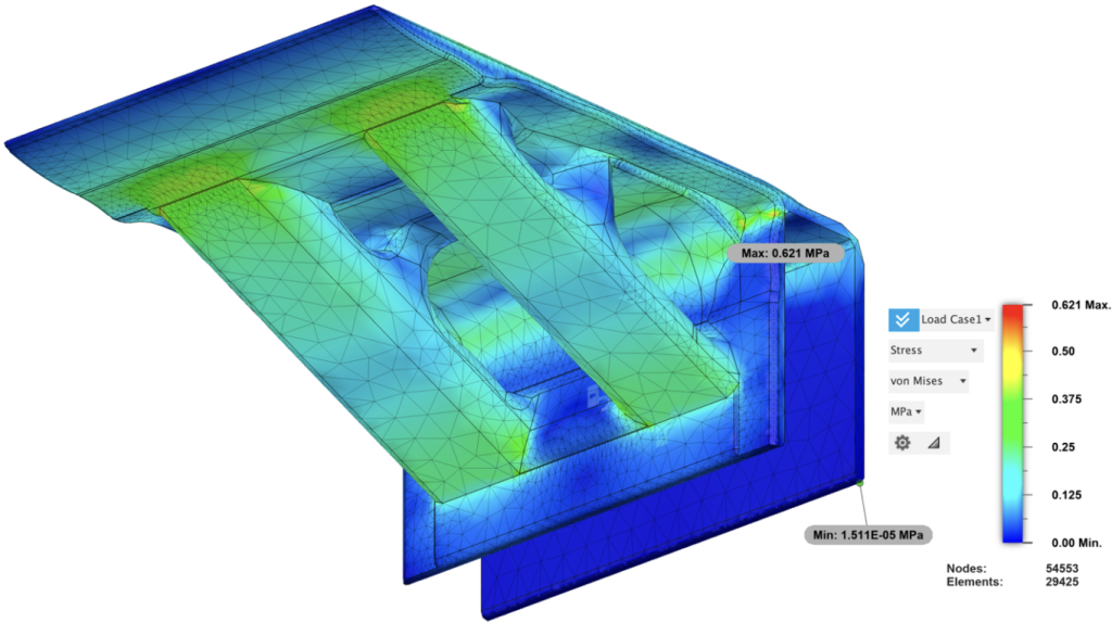
Figure 34: Static Stress Analysis (V3): Von Mises Stress
Stress in this final version is distributed more uniformly. The numerical value of the maximum stress is 0.621 MPa, showing a decrease compared to 0.675 MPa in Version 2. Unlike previous designs, there is no significant stress concentration in corners or edges. The color representation indicating stress magnitude transitions more smoothly, indicating efficient stress dispersion throughout the structure.
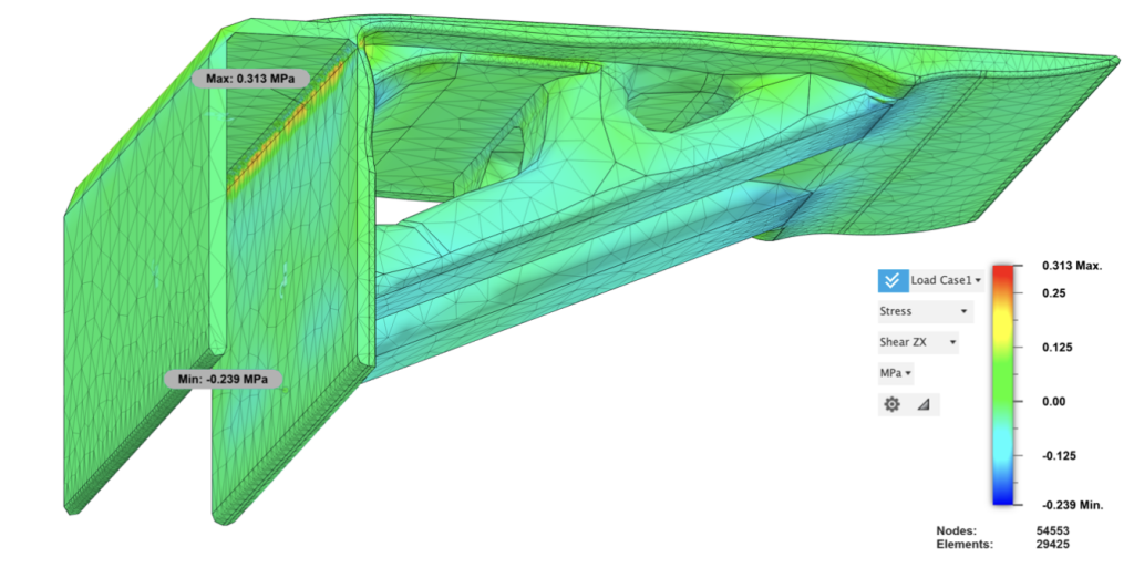
Figure 35: Static Stress Analysis (V3): Shear ZX Stress
The maximum stress is observed at the narrow edge of the clipping structure. The support is notably thin and prone to fracturing; even with an added fillet, the edges remain relatively vulnerable. As depicted above, with a maximum shear stress of 0.313 MPa in the ZX plane, concentration is evident on the rear side of the slender support area, indicating a tendency towards shearing and stretching deformation. Despite these vulnerabilities, the reduction and dispersion of stress, coupled with decreases in volume and mass, signify successful topology optimization and efficient material utilization.
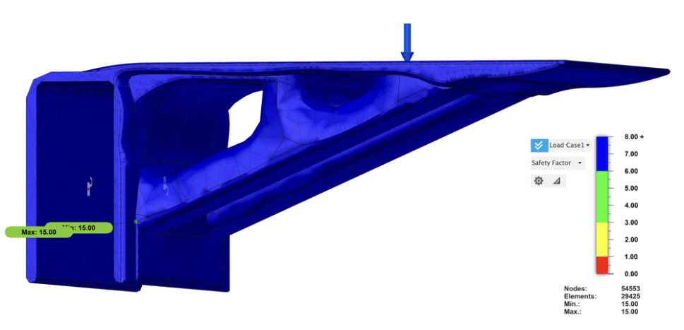
The safety factor significantly exceeds requirements, attributed to the substantial disparity between stress levels and yield strength.
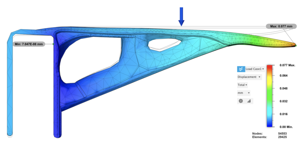
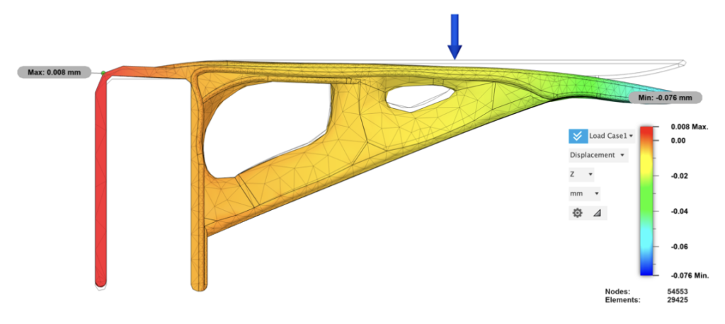
V3’s deformation is the most drastic of all versions of brackets due to minimal supporting material. Displacement at the front tip is 0.077mm, a 0.019mm inclination compared to V2. In Z axis, tail of the bracket tilted 0.008mm, a 0.005mm (168%) increase, showing the variation in deformation caused by a 20% volume subtraction.
4. Discussion and Conclusion
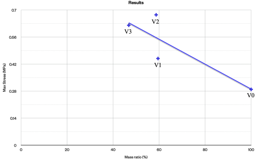
The following graph illustrates the correlation between maximum stress and mass ratio. Despite showing decreasing trend—where maximum stress increases with decearsing material— the final modification resulted(V3) in a reduction in material volume accompanied by a overall increase in maximum stress compared to V0, and a decrease compared to V2. This indicates a more even distribution of stress and an improved design.

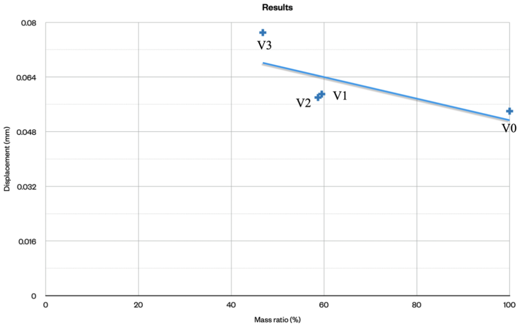
Displacement, though following a increasing trend as the verison enhances, exhibited only a very slight slope. The reductions in material did not significantly affect displacement, underscoring the impressive structural performance enhanced through topology optimization.
Through the utilization of shape optimization simulations, incorporation of fillets in corners, and other refinements, the final model exemplifies an organic and sustainable design. The design processed a 53.2% reduction in material, a saving of 719.07g of material, and an increased maximum stress by only 0.386 MPa. With the same material consumption as the initial model, 2.14 final models can be manufactured.
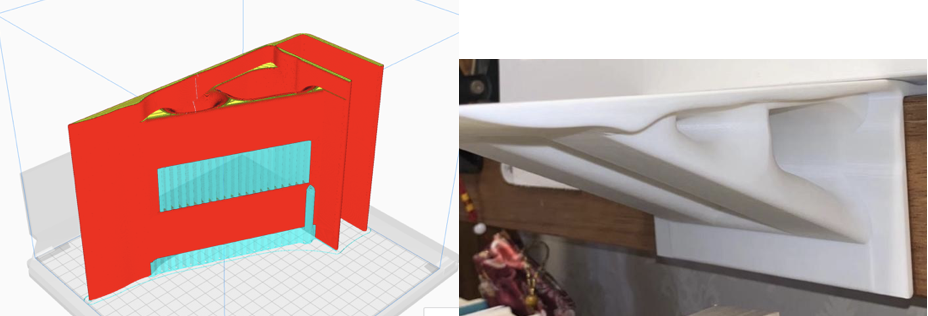
3D printing (slicing): The final design has been 3D printed, comprising 999 layers of filament with a layer thickness of 0.15 mm and a triangular grinding infill of 20%. The 3D printed bracket may exhibit slight deviations from the simulation results. These deviations are primarily influenced by vacancy of infill and irregularities caused by filament adhesion, resulting in a slightly reduced stress threshold compared to the simulated configuration.

Referring to this case of optimizing material, topology optimized products is immensely beneficiary to sustainable manufacturing and product transportation. The imperative to adopt sustainable manufacturing practices is not just a moral or regulatory obligation but a strategic imperative for the industry’s long-term viability. Embracing technologies like topology optimization offers a pathway towards achieving substantial environmental gains while unlocking new opportunities for economic growth and resilience. This approach not only aligns with global sustainability goals but also positions businesses at the forefront of innovation and competitive advantage in a resource-constrained world.
Footnotes
1 https://www.unep.org/interactive/sectoral-solution-climate-change/
2 https://www.oneplanetnetwork.org/SDG-12/natural-resource-use-environmental-impacts
3 https://www.globalgoals.org/goals/12-responsible-consumption-and-production/
4 https://www.sciencedirect.com/science/article/pii/S1000936120304520
5 https://pubs.acs.org/doi/full/10.1021/ma051022e
6 https://juggerbot3d.com/pla-filament-review/
7 https://www.sciencedirect.com/science/article/pii/S0169409X16302058
References
UN Environment Programme: The Sectoral Solution to Climate Change. https://www.unep.org/interactive/sectoral-solution-climate-change
One Planet Work Org: Natural-Resource Use and Environmental Impacts https://www.oneplanetnetwork.org/SDG-12/natural-resource-use-environmental-impacts
Global Goals Org: 12 Ensure Sustainable Consumption and Production Patterns. https://www.globalgoals.org/goals/12-responsible-consumption-and-production
Jihong Zhu, Han Zhou, Chuang Wang, Lu Zhou, Shangqin Yuan, Weihong Zhang. (2021). A review of topology optimization for additive manufacturing: Status and challenges. Chinese Journal of Aeronautics,Volume 34, Issue 1, January 2021, Pages 91-110 https://www.sciencedirect.com/science/article/pii/S1000936120304520
Kaoru Aou, Shuhui Kang & Shaw Ling Hsu, (2005). Morphological Study on Thermal Shrinkage and Dimensional Stability Associated with Oriented Poly(lactic acid) . Macromolecules 2005, 38, 18, 7730–7735 https://pubs.acs.org/doi/10.1021/ma051022e
Polylactic Acid (PLA) 3D Printing Filament Review. https://juggerbot3d.com/pla-filament-review/
Shady Farah, Daniel G. Anderson & Robert Langer. (2016) Physical and mechanical properties of PLA, and their functions in widespread applications — A comprehensive review. Advanced Drug Delivery Reviews, Volume 107, 15 December 2016, Pages 367-392 https://www.sciencedirect.com/science/article/abs/pii/S0169409X16302058
About the author
Ben Jiang
Ben is a grade 12 student from the International Campus of Beijing No. 4 High School, China. He loves delving into research on mechanics, aerodynamics and materials, as well as engaging in design and innovation. Ben is a key member of the school’s Sports Council. As the president of the basketball and lacrosse club, he has led the teams to secure the largest sponsorship ever, as well as the best ranking in Beijing International School League. In his spare time, Ben enjoys singing and street dancing. He is a pop music and jazz singer and loves letting loose and showcasing his creativity through dynamic movements.